

Pumps in Parallel: 4 Pumps
Installing several motor-driven centrifugal pumps in parallel raises water delivery on a high-volume, low-pressure scheme. Each pump draws from a common suction manifold and discharges into a common head. In practice, pumps in parallel add flow rather than pressure. This guide covers the seven installation steps, the manifold sizing arithmetic, and the mistakes that make a multi-pump station underperform.
Contents
Table of Contents
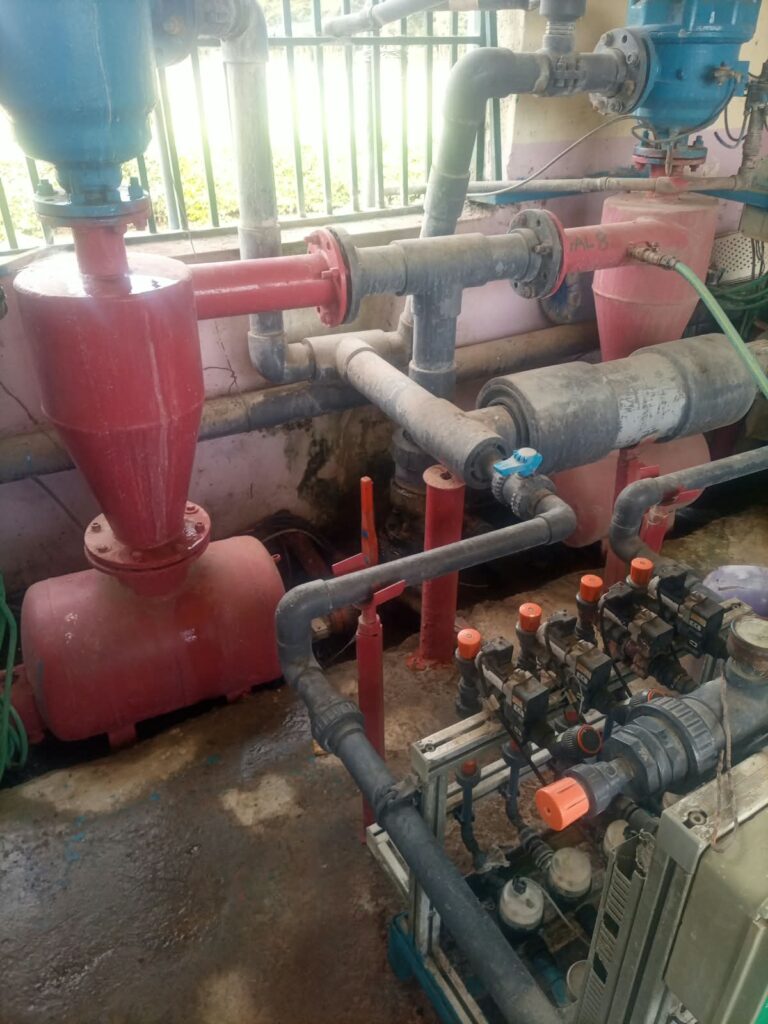
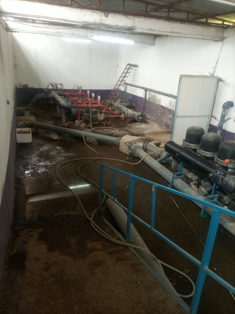
What the arrangement changes: flow, not pressure
The principle behind pumps in parallel is straightforward. Each machine adds its flow to a common discharge header. At the same time every pump works against the same total dynamic head. Consequently the station delivers more water at roughly the same pressure, which is what a large irrigation block needs.
The arrangement suits commercial farms where a single pump cannot economically deliver the required volume. It also suits schemes where demand changes with the number of blocks under irrigation. Because each pump has its own isolation valve, non-return valve and starter, the operator brings machines online as demand rises. Instead, running one oversized pump against a partly closed system wastes capacity.
A four-pump example at 400 m³ per hour
Consider a commercial farm that needs 400 m³/hour at a design total dynamic head of 30 metres. Instead of one large pump, the designer proposes four motorised centrifugal pumps. Each is selected for the duty below.
| Parameter | Specification per pump |
| Rated flow | 100 m³/hour |
| Design total dynamic head | 30 m |
| Pump efficiency | 75% |
| Calculated shaft power | 10.9 kW |
| Preliminary motor selection | 15 kW |
| Number of operating pumps | 4 |
| Total target flow | 400 m³/hour |
These figures are a preliminary duty selection. The selected pumps must be verified against manufacturer performance curves before procurement. That check includes their behaviour when running in parallel with the other machines on the same header.
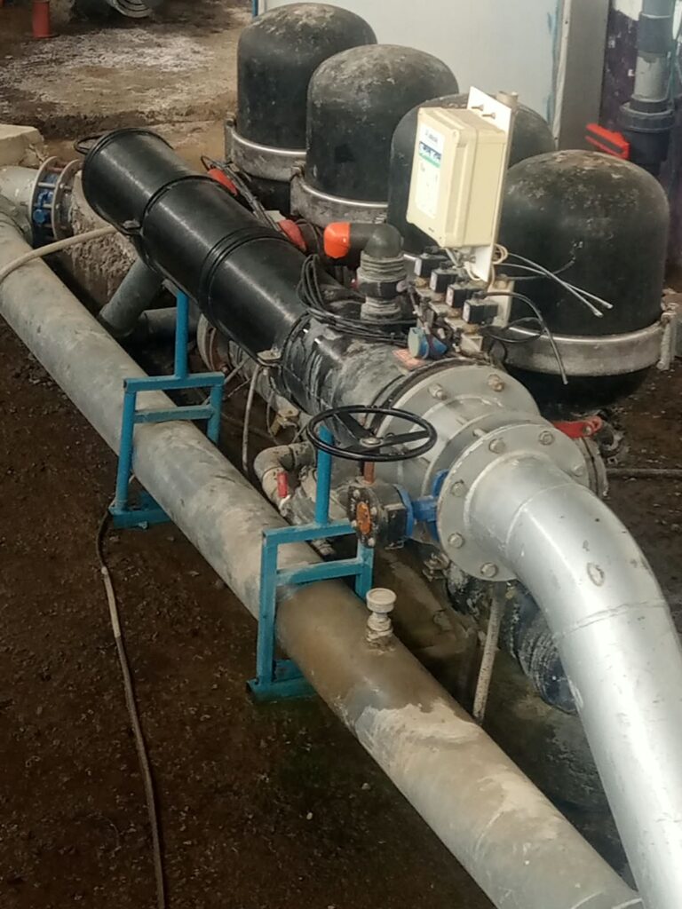
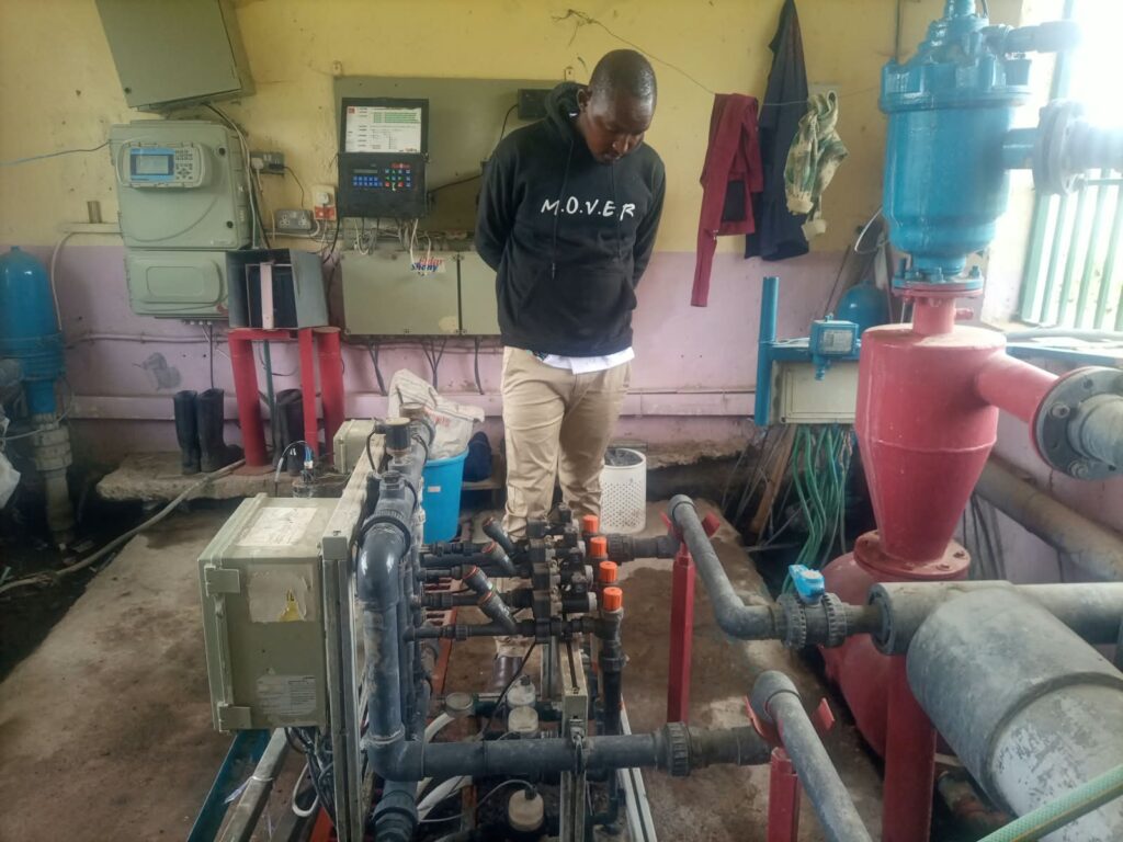
How pumps in parallel increase delivered volume
In a parallel configuration all pumps discharge into one manifold. So the theoretical combined flow at a common head is the sum of the individual flows. For the example above, total flow = 100 + 100 + 100 + 100 = 400 m³/hour.
The table below shows nominal output for one to four pumps running. It also shows the volume delivered across an eight-hour irrigation window.
| Pumps running | Nominal combined flow | Volume over 8 hours |
| 1 of 4 | 100 m³/hour | 800 m³ |
| 2 of 4 | 200 m³/hour | 1,600 m³ |
| 3 of 4 | 300 m³/hour | 2,400 m³ |
| 4 of 4 | 400 m³/hour | 3,200 m³ |
However, this does not mean that every additional pump delivers its full rated capacity. The final operating flow depends on two things. It depends on the combined pump curve, and on the resistance of the connected pipeline network. For that reason, treat the numbers above as nominal additions at a common 30 m head. Then confirm the actual system flow from the manufacturer curves and the system curve.
Step-by-step installation of pumps in parallel
The installation of pumps in parallel follows the same sequence on a four-pump station as on a two-pump one. First the civil works, then the hydraulics, then the electrical side. Commissioning comes last.
- Construct the pumping station. Select a site close to the reservoir. Preferably use a flooded suction arrangement, which improves priming and reduces cavitation risk. Then construct reinforced concrete foundations with adequate anchoring, alignment provisions and drainage.
- Install the common suction manifold. Size the manifold to the reservoir intake and to the combined flow, not to a single pump. For the example, a combined flow of 400 m³/hour equals 0.1111 m³/s.
- Install individual pump suction branches. Connect each pump to the common suction manifold with properly sized branches, isolation valves and suitable fittings. Avoid unnecessary elbows close to the pump suction. Also confirm sufficient net positive suction head available at the lowest reservoir operating level.
- Install the discharge manifold. Each discharge branch should carry a non-return valve, an isolation valve and a pressure measurement point. All branches then connect to the common discharge header. That header feeds the filtration system and the main irrigation network.
- Install the electrical and control systems. Provide each pump with motor protection, a suitable starter or variable-frequency drive, overload protection and emergency isolation. Meanwhile the controller should permit sequential pump starting and stopping. This reduces electrical demand peaks and hydraulic surges.
- Integrate filtration and fertigation. The combined discharge should pass through appropriately sized filtration before entering the field network. Specifically, integrate the fertigation unit downstream of primary filtration. Provide backflow prevention and dosing interlocks.
- Commission the installation. First, commission pumps individually before testing combined operation. Then measure discharge pressure, actual flow, motor current, vibration and filter pressure differential. Finally, confirm the station delivers the required flow without exceeding motor ratings or causing unacceptable pressure fluctuations.
Sizing the suction manifold
Typically, suction sizing is where a parallel station most often goes wrong. The manifold must carry the sum of the flows, not the flow of one pump. At an illustrative suction velocity of 1.2 m/s, the arithmetic gives D = √(4 × 0.1111 ÷ (π × 1.2)) = 0.343 m. So the suction manifold needs approximately 343 mm internal diameter at that assumed velocity.
A suitable commercial pipe size must then be chosen using its actual internal diameter, since nominal sizes differ between pipe classes. Next, check the suction side against the pump’s own limit. The NDSU Extension guide to irrigation water pumps explains how fittings on the suction side, such as elbows and foot valves, combine with the net positive suction head published on the pump curve to set how hard a pump can lift.
Pumps in parallel compared with pumps in series
This distinction matters during irrigation design, because the two arrangements solve different problems.
| Arrangement | Primary engineering effect | Typical application |
| Pumps in parallel | Increases available flow capacity | High-volume irrigation |
| Pumps in series | Increases available delivery head | High-elevation or high-pressure systems |
For example, take two identical pumps rated at 100 m³/hour and 30 metres head each. Operating in parallel, they may theoretically deliver 200 m³/hour at 30 metres. That holds only if the system can accommodate the extra flow. By contrast, connected in series, the same two pumps may reach approximately 60 metres of head at 100 m³/hour. Actual results depend on pump curve characteristics and system operating conditions.
Why adding more pumps can disappoint
Adding pumps without upgrading the rest of the system often produces disappointing results. The reason is friction: losses rise as flow rises. So the manifolds, delivery pipelines, filtration infrastructure and control systems all have to grow with the station. Therefore the correct engineering approach is to design the reservoir, pumping station, filtration system, mainline and distribution network as one coordinated hydraulic system.
For large schemes we recommend a duty and standby configuration, which improves operational reliability. Variable-frequency drives suit schemes where variable demand justifies speed control. Each pump should have independent isolation and non-return valves, and the station needs pressure sensors and flow meters so its real performance can be measured rather than assumed. Surge analysis and suitable pressure protection should be completed before procurement.
Similarly, the same discipline applies upstream of the pumps. Our work on irrigation reservoir construction starts from the abstraction rate, because a reservoir that cannot refill at that rate caps everything the station can deliver.
Frequently asked questions about pumps in parallel
Do pumps in parallel double the pressure?
No. Pumps in parallel add flow against a common discharge head. So pressure stays close to that of a single pump. If you need head rather than volume, use series operation.
Can I run only one pump from a four-pump station?
Yes, and that is the point of the layout. Each pump has its own isolation valve, non-return valve and starter. So the operator brings machines online as demand rises.
Will each extra pump give me its full rated flow?
Not always. The combined pump curve sets the operating point. The resistance of the pipeline network matters just as much. So the rated flow of each machine is a starting point, not a guarantee.
How do I size the manifold for pumps in parallel?
Size it for the maximum simultaneous flow, not for one pump. In the worked example, 400 m³/hour at a suction velocity of 1.2 m/s needs roughly a 343 mm internal diameter suction manifold.
Is this arrangement cheaper than one large pump?
Often, on high-volume low-pressure schemes. Several standard-duty machines avoid one oversized unit and give staged capacity. Verify the selection against manufacturer curves before deciding.
Does the same logic apply to solar pumping?
Partly. Solar systems are usually sized around available array power, so staged pumping looks different there. See our guide to solar irrigation systems for how we phase those installations.
Where to have pumps in parallel installed in Kenya
Eunidrip Irrigation Systems Ltd designs and installs integrated high-volume irrigation infrastructure. Our scope runs from preliminary survey and hydraulic calculations to installation, testing and commissioning. Our page on pump selection for irrigation covers how a single duty is chosen before a station is built. The irrigation solutions page sets out the systems we supply.
Call +254 728 163329 or +254 724 775516, email eunidrip@gmail.com, or use the contact page. Send your target delivery volume, the static head, and the number of blocks you intend to run at once.